UPDATE: Now shipping worldwide from SchneidersLaden 🇪🇺 and CrowdSupply 🇺🇸!
Tiliqua is a powerful, hackable FPGA-based audio multitool for Eurorack.
Check out the Documentation, GitHub Repo.
Overview
Tiliqua aims to make FPGA-based audio and video synthesis accessible. With fully reconfigurable hardware and a rich suite of example projects built in Python (Amaranth HDL), Tiliqua allows you to experiment with synthesis techniques out of reach of embedded microcontroller-based platforms. Think extreme oversampling for alias-free audio-rate modulation, low-latency effects, video synthesis, high-speed USB audio, or emulating retro hardware.
Designed for Live Performance
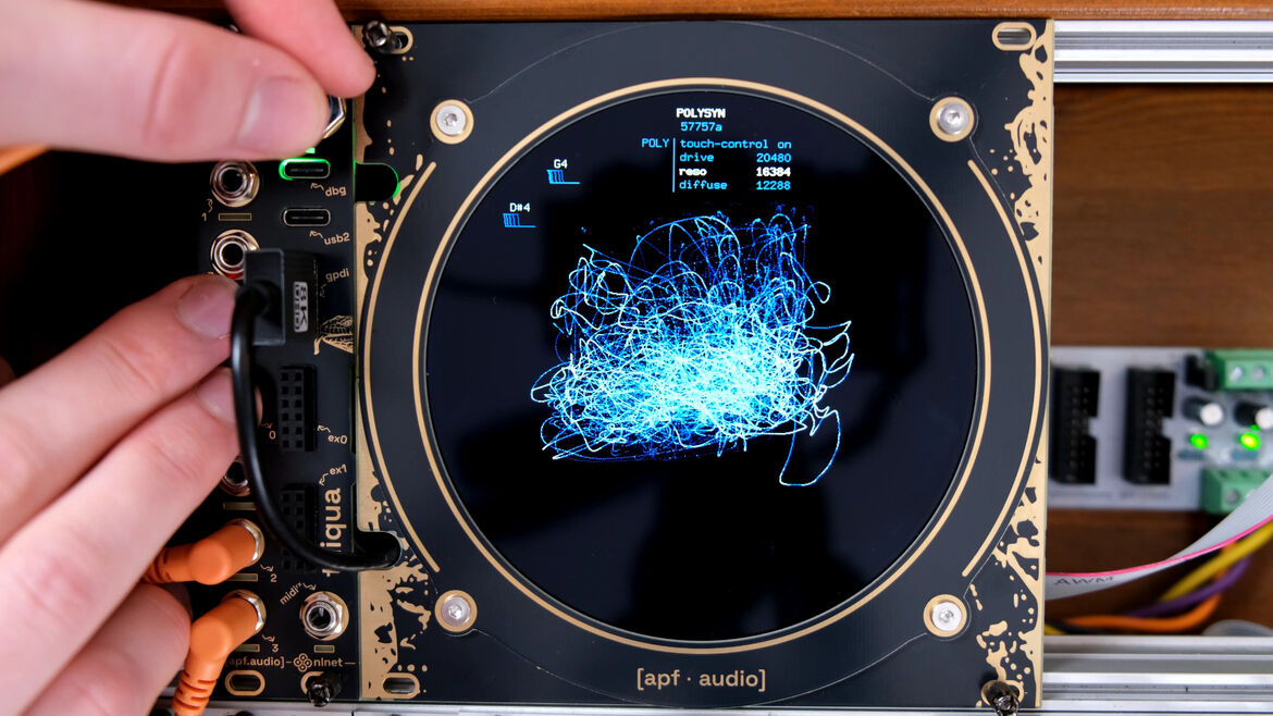
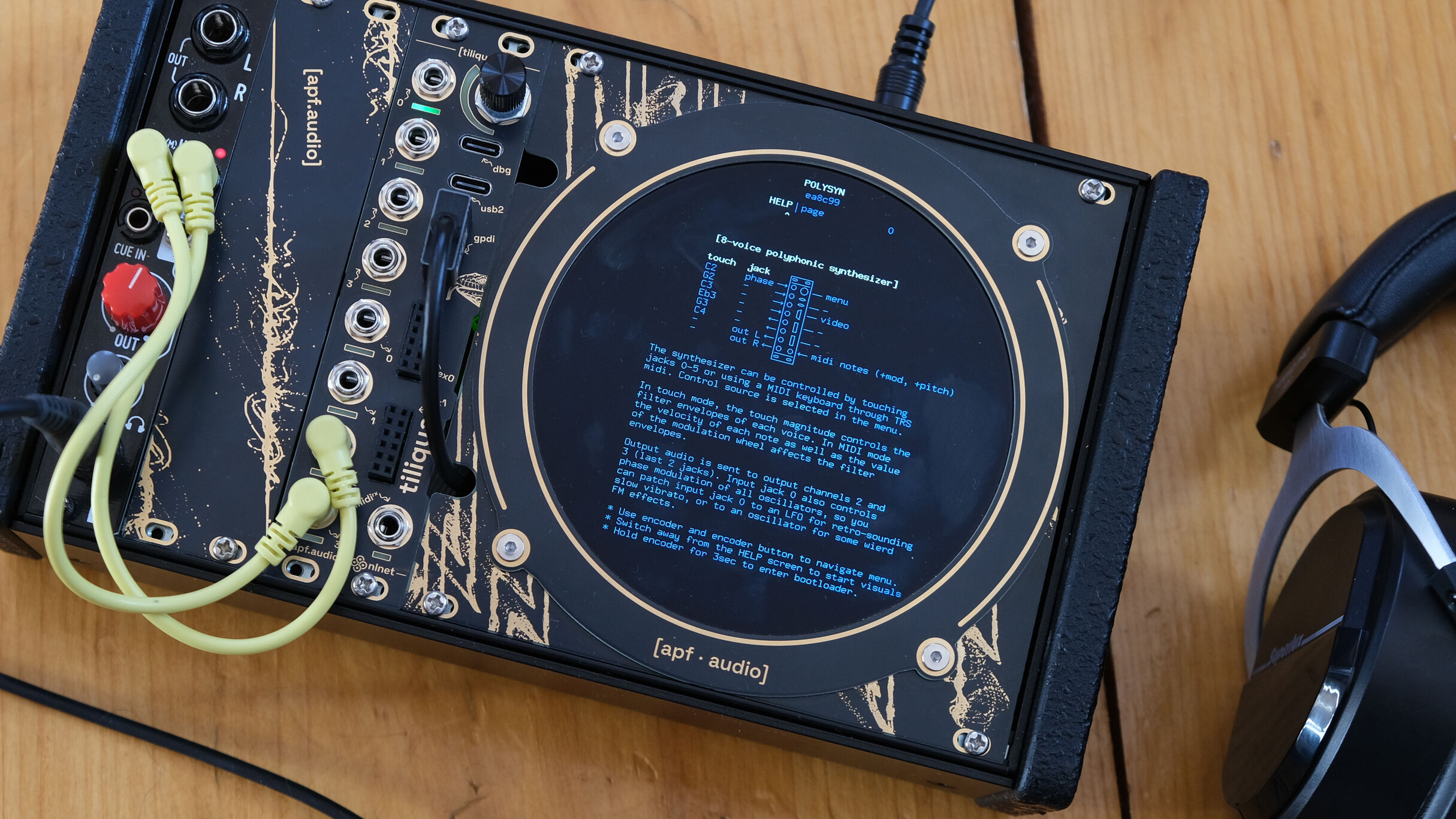
Switch between eight customizable projects (bitstreams) on the fly. Tiliqua will soft-mute the outputs while the hardware is reconfigured. From polyphonic synthesizer to multi-channel oscilloscope, from USB audio interface to complex modulation source — transform the hardware instantly with a twist of the encoder, no computer required.
Optionally, connect a computer to customize what designs are in each Tiliqua slot using a web browser. Each design rewires how Tiliqua's internal sea of logic gates is connected, for limitless audiovisual possibilities.
More than Audio
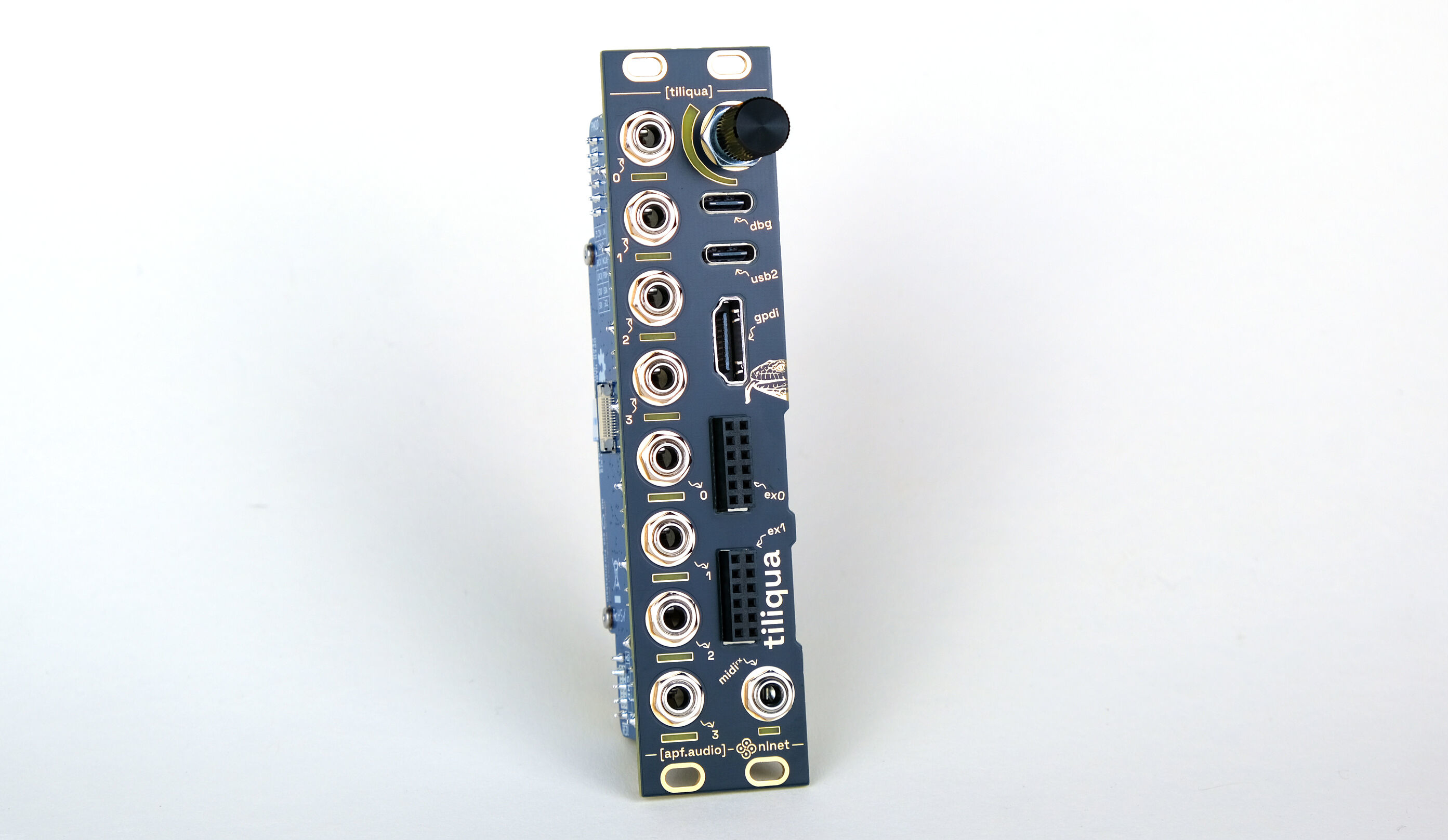
Touch-sensitive jacks and flexible I/O can turn Tiliqua into an instrument unlike any other in your rack. Connect any display to unlock visual synthesis capabilities that sync perfectly with your audio creations. With 8 high-fidelity DC-coupled audio channels (4 in, 4 out), high-speed USB (host or device), display and MIDI connectivity, as well as 2 PMOD-compatible expansion ports, Tiliqua provides enough connectivity for the craziest of ideas.
An Open Platform
More than another module; Tiliqua is a development platform. The Python-based DSP library aims to make audio hardware development accessible even for those less experienced in FPGA design. Every piece of hardware, software and gateware in the Tiliqua project can be opened, modified, re-synthesized or re-manufactured using open-source tools. Easily flash and share projects using the built-in RP2040-based debugger exposed on the front panel.
Out of the Box Demos
Tiliqua comes with a rich suite of demo projects for getting started:
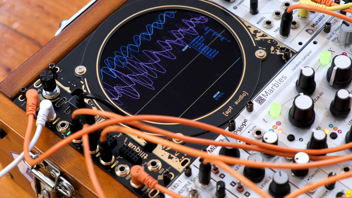
polysyn: 8-voice polyphonic synth with video visualization and MIDI and USB hostxbeam: 4-channel oscilloscope and signal visualizerusb-audio: 4-in, 4-out, USB2 high-speed soundcardmacro-osc: complex multi-harmonic oscillatorsid: chiptune simulationselftest: health-check and automatic DC offset calibration- And many more DSP-only examples (reverb, pitch shifting, delay lines and so on).
As the project develops and with community contributions, we hope to add many more.
Technical Specifications
- FPGA: Lattice LFE5U-25F-6BG256, fully supported by the open source FPGA flow
- RAM: 32MByte PSRAM (tested up to 200MHz DDR for 400MByte/sec)
- Audio: 8x multifunction jacks (4 in, 4 out):
- 192kHz sample rate
- DC-coupled, for audio or CV
- Insertion detection on all jacks
- Capacitive touch sensing on all unused jacks
- Read/green indicator LEDs on all jacks
- Inputs have:
- 100K input impedance
- +/- 9V input range
- <5mV absolute DC accuracy (from 0 to +5V, when calibrated)
- Outputs have:
- Soft mute on bitstream changes
- 1K output impedance
- +/- 8V output range
- <5mV absolute DC accuracy (from 0 to +5V, when calibrated)
- USB: two ports:
- One High-Speed (480Mbit/s) connected to FPGA. Both device and host mode are supported.
- One Full-Speed (12Mbit/s) to RP2040 compatible with
openFPGALoaderfor flashing. Host mode is not supported on this port.
- Encoder: rotary, with pushbutton and LED bargraph display
- Video: Digital video ("gpdi": General Purpose Differential Interface) including 3.3V to 5V bidirectional I2C level shifter. Max resolution 1280x720p/60Hz.
- Expansion: 2x PMOD-compatible expansion ports for up to 24 simultaneous audio channels. All 16x 3.3V pins directly connected to the FPGA. 4 of these pins are shared with spare RP2040 pins.
- MIDI: Optoisolated TRS-A MIDI input.
- Debugger: RP2040, supported by openFPGALoader
- Storage:
- 16MByte SPI flash: for the FPGA
- 16MByte SPI flash: for the RP2040
- 2Kbit I2C EEPROM: for storing calibration constants
- External PLL (SI5351A) for dynamic display resolution switching and spread spectrum.
- Mechanical specifications:
- 3U tall, 6HP wide, standard Eurorack module form factor.
- 34mm deep including power ribbon cable.
- Power supply requirements:
- 10-pin Eurorack power
- +12V: 150mA (or 400mA as USB host with device drawing 500mA at +5V)
- -12V: 20mA
Gateware Design
Tiliqua's example projects make heavy use of the abstractions provided by Amaranth HDL, allowing each component to be connected together with streams. To give you a taste, the following Python code implements a DSP pipeline which operates on 16-bit fixed-point samples, adding a sawtooth oscillator, followed by a waveshaper and delay effect, and then connecting them together:
class ExampleDspComponent(wiring.Component):
    i:  In(stream.Signature(fixed.SQ(f_width=15)))
    o: Out(stream.Signature(fixed.SQ(f_width=15)))
    def elaborate(self, platform):
        m = Module()
        # Create some DSP blocks ...
        nco     = dsp.SawNCO()
        shaper  = dsp.WaveShaper(
            lut_function=sine_osc, lut_size=128, continuous=True),
        delay   = dsp.DiffusionDelay()
        # Connect them together ...
        wiring.connect(m, flipped(self.i), nco.i)
        wiring.connect(m, nco.o, shaper.i)
        wiring.connect(m, shaper.o, delay.i)
        wiring.connect(m, delay.o, flipped(self.o))
        m.submodules += [nco, ws, rs]
        return m
This would construct some hardware connections like this:
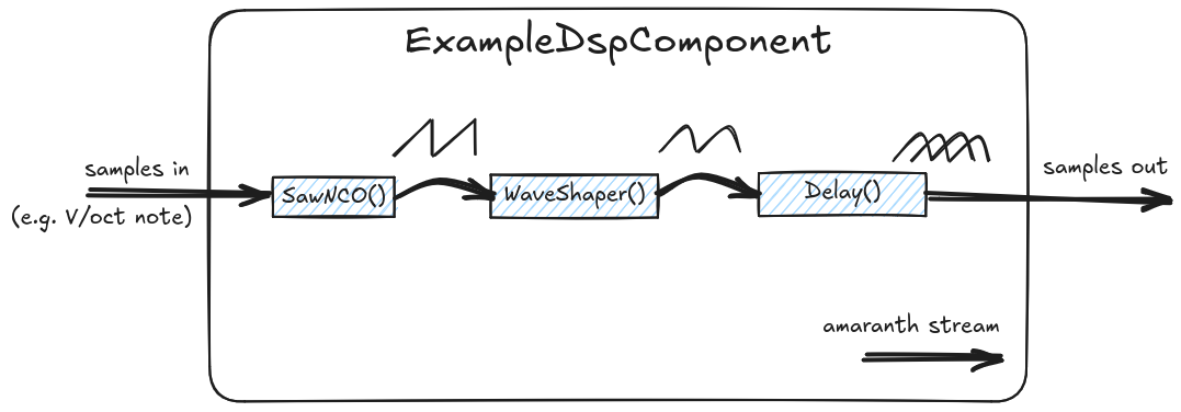
In Tiliqua's examples and DSP library, you will find simpler examples (oscillators, delay, reverb, pitch-shifting), as well as more complex examples where a RISC-V CPU is instantiated to run a menu system and tweak parameters of the hardware DSP pipeline in real time. All of this already implemented, what remains is adding more DSP components to the existing library, more examples, and more documentation to make Tiliqua even more capable. Purchasing a Tiliqua from us is the best way to make this happen!
Hardware Design
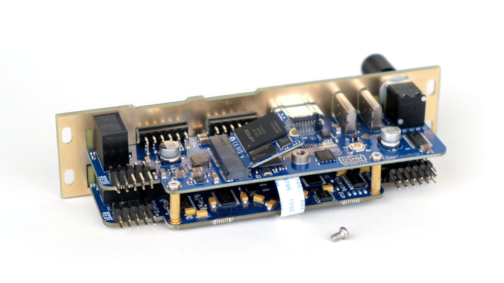
The Tiliqua hardware is composed of 3 core PCBAs, pictured below:
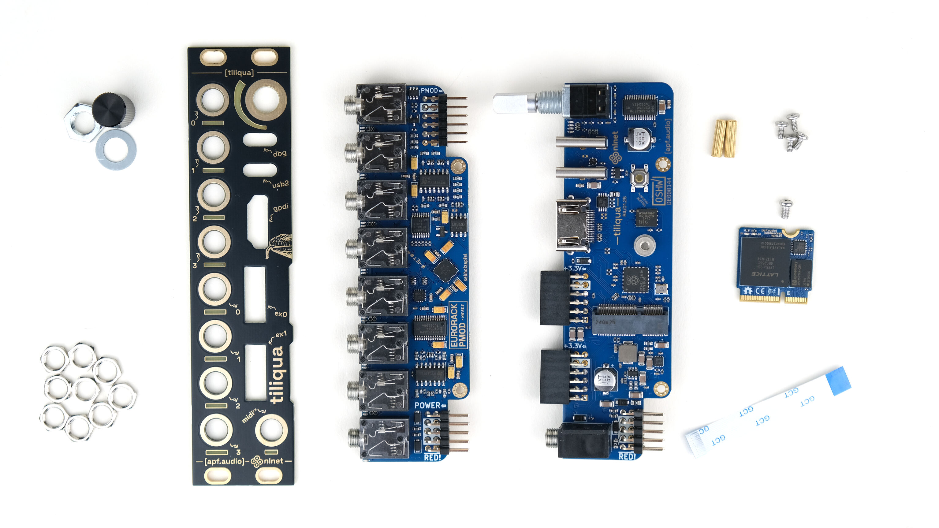
Tiliqua itself is modular—the FPGA core (an integrated System-on-Module in M.2 form factor) can be removed and embedded in your projects. The audio interface section is PMOD-compatible, and can be removed and connected to other FPGA development platforms.
Block Diagram
Below is a simplified view of how all the different parts of Tiliqua are connected:
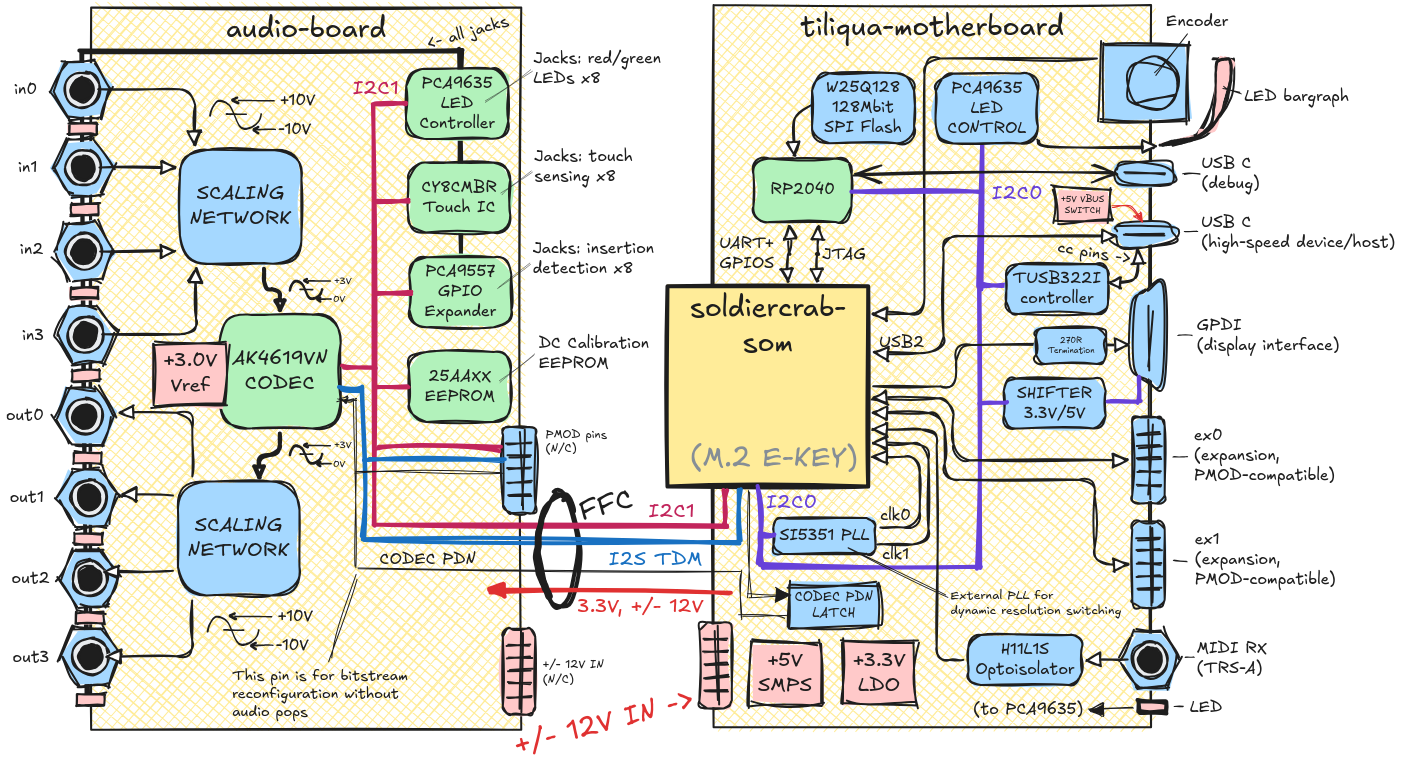
Now we shall take a more detailed look at each part of Tiliqua.
Embedded FPGA SoM "SoldierCrab"
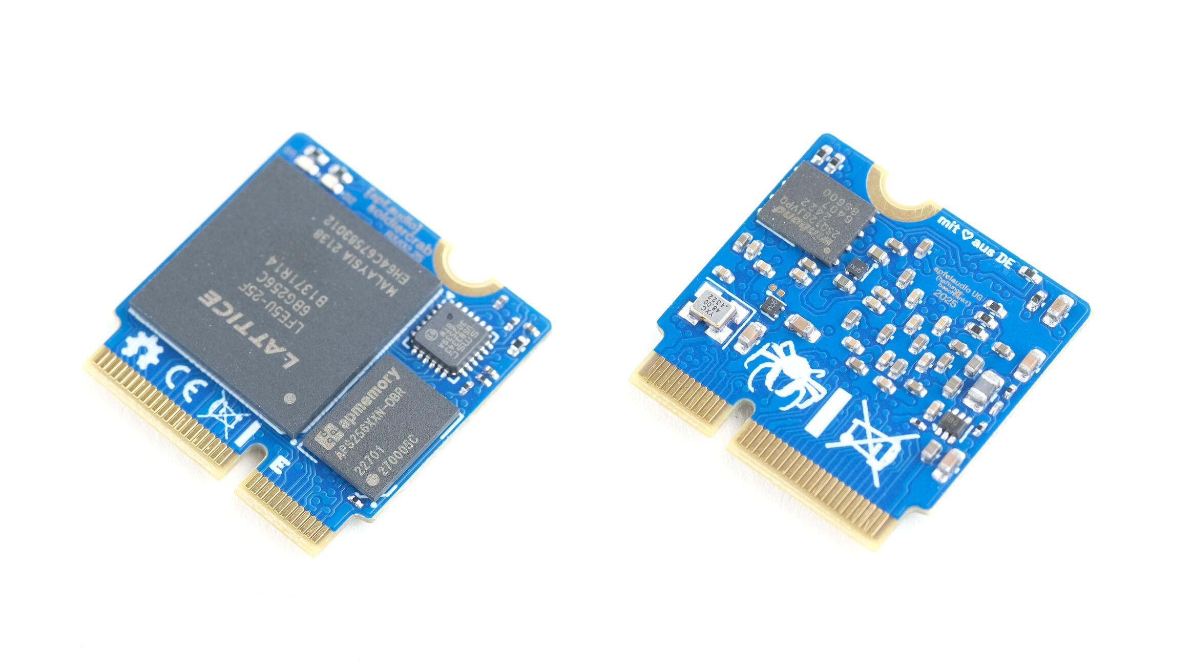
SoldierCrab is the heart of Tiliqua. It contains an FPGA, RAM, SPI Flash, High-Speed USB PHY and support components. It can be removed and replaced with a single screw, and has a mechanical form factor and pinout very similar to Sparkfun's MicroMod ecosystem (the JTAG pins are different as the ECP5 does not support SWD, so we cannot claim compatibility, even if a USB bootloader would get us most of the way there!). You can find detailed documentation on this module in the SoldierCrab repository. The most important parts:
- LFE5U-25F-6BG256C FPGA: 25K LUTs, supported by open source toolchains.
- APS256XXN-OBR oSPI-RAM: tested up to 200MHz, 400MByte/sec. This part is pin-compatible with HyperRAM, so it should be easy to swap RAM chips if we have supply chain problems.
- USB3343 USB PHY: 480Mbit/sec, with exposed ID, useable in device or host mode
- 25Q128 SPI Flash: 16Mbyte of storage for bitstreams, firmware or whatever you want
- 2 indicator LEDs on the PCBA
- 48MHz master clock
- 22mmx22mm board size with M.2 E-key card edge
- Card edge is 47 exposed general purpose pins + 4-pin JTAG + USB2
Tiliqua Motherboard
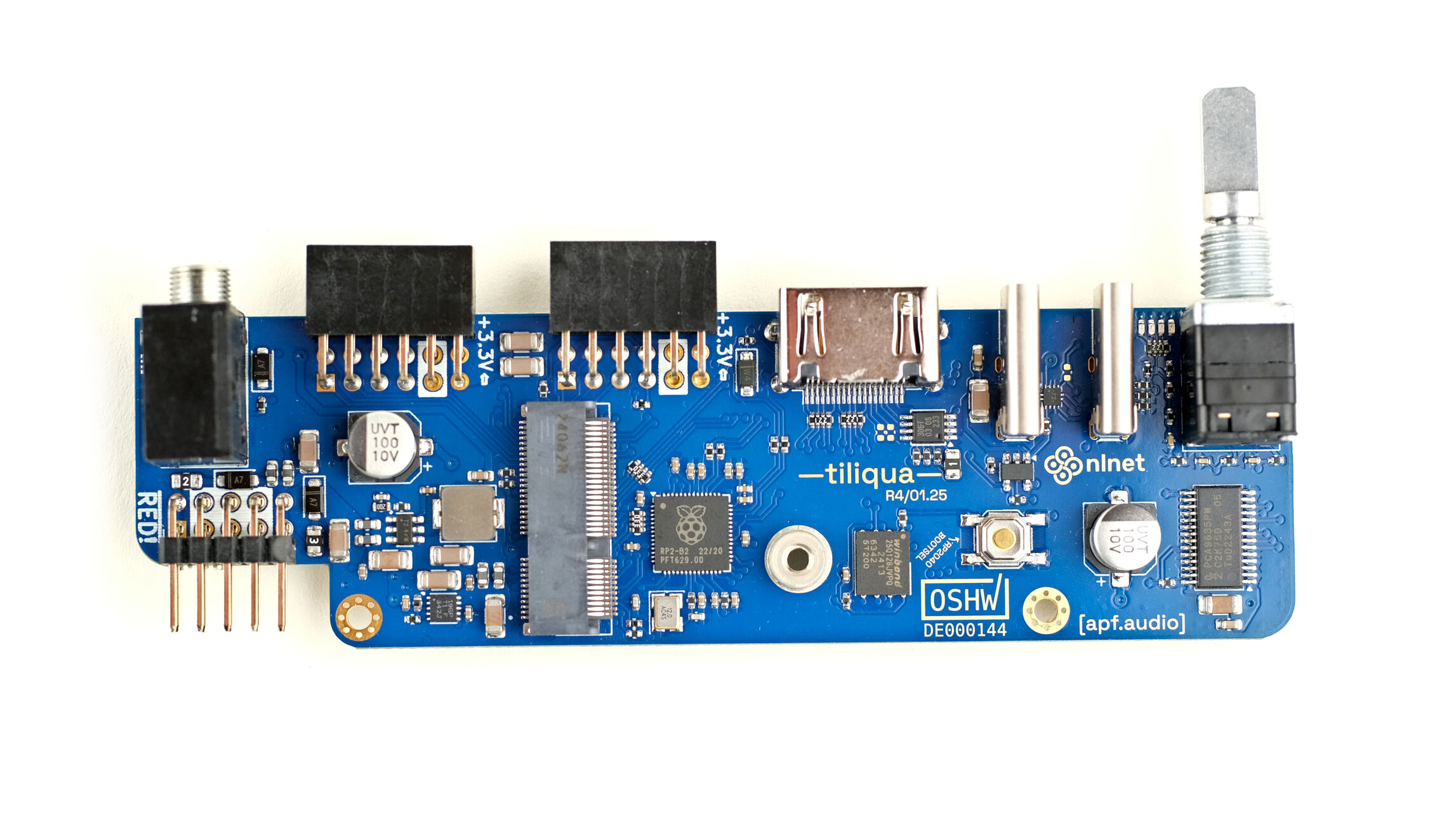
Tiliqua's motherboard contains most of the connectivity options and acts as a bridge between the FPGA SoM and the audio interfaces. It contains Tiliquas main power supplies, RP2040-based debugger, LED and USB CC controllers and MIDI optoisolator. The Tiliqua motherboard also has an external PLL which can be used for dynamic display resolution switching, as well as circuitry for soft mute across reconfigurations.
Audio Board (Eurorack PMOD)
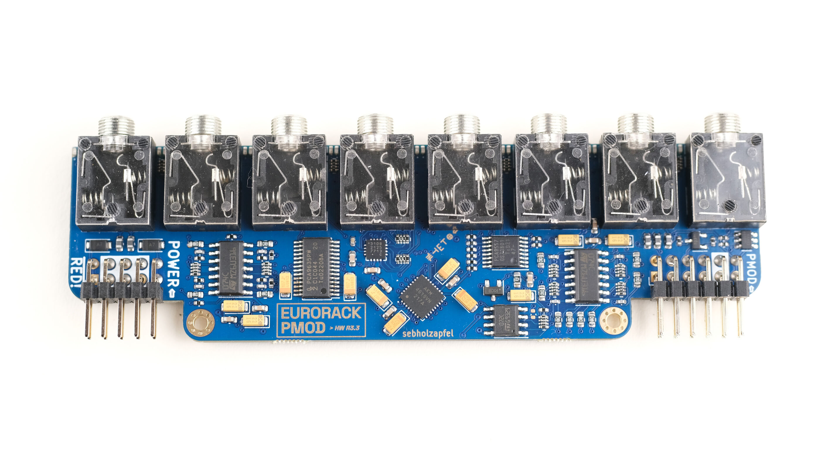
Tiliqua's audio board can be used both inside the Tiliqua (as shipped) or independently as an expansion board for more channels.
- Inside the Tiliqua, both 0.1" headers are left unconnected, and the audio and power supply connections are over FFC.
- Outside the Tiliqua, the audio board can be used independently with a standard 10-pin Eurorack cable and 12-pin ribbon cable as a PMOD expansion module - either for the Tiliqua itself (for up to 24 simultaneous audio channels), or for other supported FPGA development boards.
At the heart of the audio board is an AK4619VN audio CODEC (I2C and I2S interface), op-amp scaling network, voltage reference and supporting components. This board also includes the CY8CMBR capacitive touch sense IC, PCA9557 for jack insertion detection and PCA9635 for PWM LED control.
Expansion
Using the 2 expansion headers, Tiliqua can be augmented with:
- Extra audio sections for up to 24 simultaneous audio channels (1 internal + 2 external audio sections = 3 * 8 channels)
- Existing boards from the PMOD ecosystem, like LED panel drivers, SD card readers, and so on
- Anything that uses 3.3 V logic levels for communication